Are RMS current and THD enough to judge transformer heating under harmonic loads?
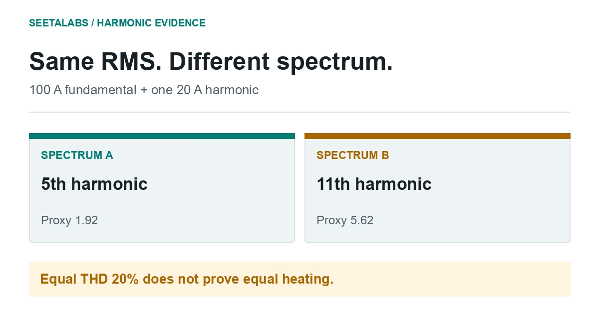
No. Two currents can share RMS current and THD while carrying distortion at different harmonic orders, and RMS cannot describe all frequency-dependent heating. For example, a 100 A fundamental with 20 A at the fifth harmonic, or at the eleventh, gives the same 20% THD but a very different illustrative frequency-weighted value. Obtain per-phase harmonic spectra across relevant operating states and the transformer’s loss data before judging capability.
Two current spectra can share RMS current and THD while placing distortion at different harmonic orders. RMS informs resistive loss but cannot describe all frequency-dependent transformer heating. Obtain spectra across relevant operating states before judging capability.
What RMS and THD Leave Out
RMS combines fundamental and harmonic components. Equal RMS and THD do not identify which harmonic orders carry the current.
IEEE C57.110-2018 addresses transformer capability under nonsinusoidal currents. Its official scope, not full equations or application requirements, was reviewed. The teaching calculation below is not a rating method.
The 2022 author preprint models power-electronic loads; its abstract is research context, not field validation of a loading limit. No result from it is used in the example.
A harmonic-tolerant design need not mitigate the plant's harmonics.
A Worked Comparison With Identical RMS Current
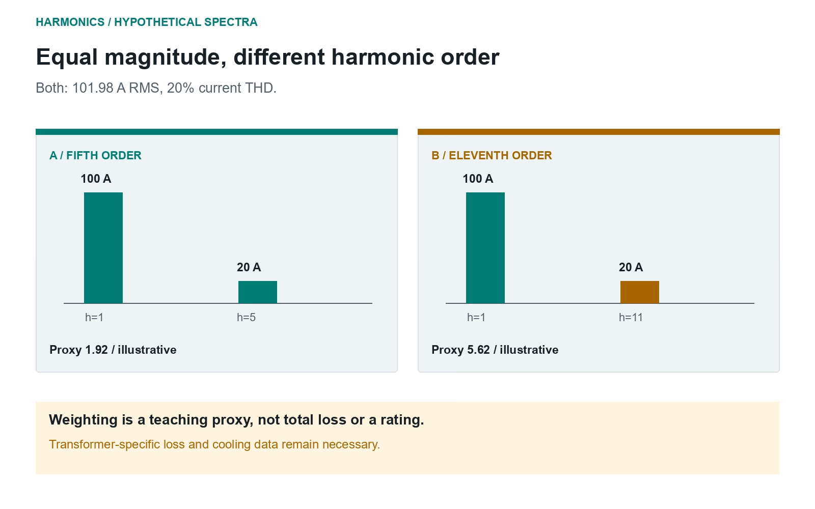
Hypothetical: both currents have a 100 A fundamental and one 20 A harmonic: the fifth in A, the eleventh in B.
Both have RMS current sqrt(100^2 + 20^2) = 101.98 A and current THD 20/100 = 20%.
For an illustrative frequency-sensitive proxy, divide the sum of h^2 times each squared current by total squared current. This is not a standard loss or rating calculation.
The common denominator is 100^2 + 20^2 = 10,400 A^2. Spectrum A's numerator is 100^2 + 5^2 x 20^2 = 20,000; B's is 100^2 + 11^2 x 20^2 = 58,400. Dividing gives about 1.92 and 5.62. The weighting is dimensionless and deliberately omits transformer-specific loss coefficients.
| Quantity | Spectrum A | Spectrum B |
|---|---|---|
| Fundamental current | 100 A | 100 A |
| Harmonic current | 20 A at order 5 | 20 A at order 11 |
| Total RMS current | About 102 A | About 102 A |
| Current THD | 20% | 20% |
| Illustrative weighted numerator | 20,000 | 58,400 |
| Normalised illustrative weighting | About 1.92 | About 5.62 |
The different proxy values do not imply that total loss, hot-spot temperature or ageing changes in the same proportion. Winding geometry, loss components and cooling matter.
Neither value selects a K-rating.
Specify a Survey That Answers the Loading Question
Measure representative plant states, including relevant partial-load operation, with phase identification and a stated measurement basis.
Request per-phase RMS and individual harmonic currents, voltage conditions, aggregation period and equipment roster. Check whether neutral or circulating currents matter for the winding connection. Retain instrument configuration and frequency range.
Obtain transformer loss data, winding connection, rating, cooling and temperature history. Terminal current alone cannot resolve every local heating effect. State unavailable design details rather than inventing loss components.
The condition-monitoring record and DGA history add context, but cannot reconstruct a missing spectrum.
Read the Study's Conclusion Carefully
Report measured operating states, spectrum, method, transformer data and gaps. Distinguish assessment of an existing unit, replacement or mitigation.
Check mitigation at relevant load states and temperature assumptions against installed cooling. One harmonic indicator is not an operate-or-stop instruction.
If a recommendation uses only RMS and THD, ask how it distinguishes the two examples.
Sources and scope: IEEE C57.110-2018 official edition and scope rechecked 29 September 2026; full text not read. Mitra and colleagues, arXiv:2210.14824, abstract and version history read 29 September 2026, full method not reviewed. Spectra and weighting are original educational calculations, not standard examples or paper results.