
Top-oil temperature does not measure the winding hot spot. A hot-spot value may itself be modelled, indicated indirectly or measured at an installed sensor location. Keep the signal and its provenance visible before comparing it with an independently established loading limit.
Identify the Temperature Before Interpreting It
IEC 60076-7:2018 addresses mineral-oil transformer loading. A fixed allowance added to top oil cannot represent every changing load and ambient-temperature condition.
Read the instrument documentation. A winding-temperature indicator may simulate a winding rise; an embedded fibre-optic sensor measures its installed location, not automatically the limiting spot. The Bureau of Reclamation manual, section 4.3, distinguishes winding indication from direct measurement.
This original table identifies the evidence behind each signal.
| Signal | What the label should clarify | Question before using it for loading |
|---|---|---|
| Top-oil temperature | Sensor position and calibration status | Does the value represent the intended oil location? |
| Winding-temperature indicator | Instrument model and thermal simulation | Are its settings appropriate for this winding? |
| Calculated hot spot | Model, inputs and parameter version | Has the model been checked against relevant tests or observations? |
| Fibre-optic temperature | Sensor location and channel identity | What parts of the winding are not measured? |
| Ambient temperature | Measurement location and exposure | Does it represent the cooling-air inlet conditions? |
Separate a Thermal Calculation From Permission to Load
The thermal model needs consistent load, cooling state, starting temperature and ambient inputs. A model configured for working cooling can mislead when fans or pumps are unavailable.
Record whether cooling status was measured or assumed. Record the permissible temperature separately, with its source, loading category, duration and unit-specific basis. Assess bushings, leads, tap changers and circuit constraints separately; a winding calculation cannot establish their capability.
IEEE C57.91-2025 is a published loading guide; only its official scope and edition were reviewed here. Do not mix procedures without an engineering basis.
Worked Example: Equal Top Oil, Unequal Evidence
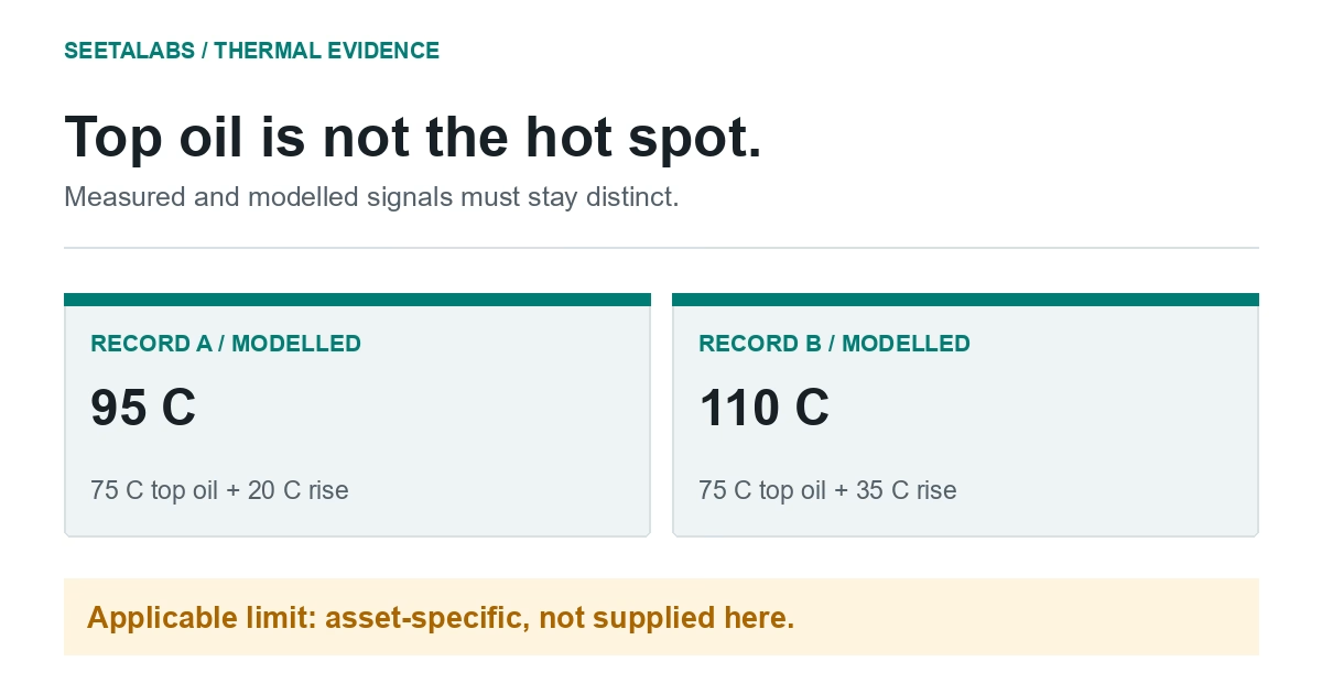
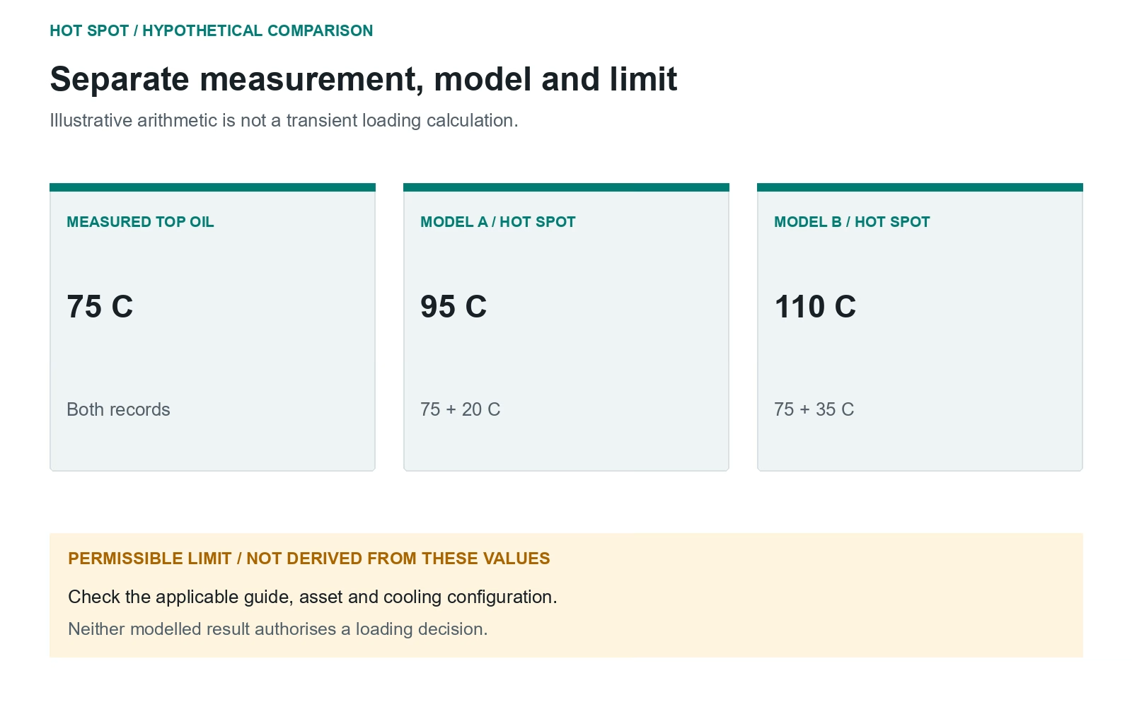
Hypothetical, not loading limits: both records have top oil at 75 degrees C. Model A estimates a 20-degree hot-spot rise; model B estimates 35 degrees. The illustrative sums are 95 and 110 degrees C.
Identical top oil need not mean identical hot spots. The values are not standard parameters, alarms or permission to load. A real transient assessment needs the applicable model, limits and other equipment constraints.
If B's cooling tag has remained unchanged for days, verify the tag and channels against load and temperature history before attributing the difference to insulation deterioration.
Compare predictions with tests and comparable operation. An unexplained residual prompts investigation; it does not identify a unique fault.
The DGA guide offers related chemical evidence, not a direct hot-spot measurement.
Make the Limiting Assumption Visible
Before a report reaches operations, reconcile the historian tags with the instrument list and cooling schematic. Keep signal types, model, parameters, starting condition, duration and separately checked constraints with the condition-monitoring record.
Sources and scope: IEC 60076-7:2018 and IEEE C57.91-2025, official scopes rechecked 29 September 2026. IEC clauses 7, 8.1 and 8.2 were checked in a licensed local copy in the earlier review; IEEE full text was not available. Bureau of Reclamation (2005), section 4.3, supports the instrument distinction from the earlier review; its PDF was not newly accessible. Table and example are original, not loading approvals.