Does higher winding resistance at a later test mean a deteriorating connection?
Not necessarily. Higher resistance can reflect temperature, a different current path, an unstable reading or a deteriorating connection, so compare the same terminal pair and tap on a traceable temperature basis. Correct to a reference temperature with the factor in IEC 60076-1:2011, Annex E (K = 235 for copper, 225 for aluminium), then check whether the change is common to all phases and taps or local to one position.
Higher winding resistance may reflect temperature, a different current path, an unstable reading or a deteriorating connection. Compare the same terminal pair and tap on a traceable temperature basis, then check whether the change is shared across positions or local to one tap.
This guide reviews results. DC testing stores magnetic energy: leads must remain connected until the prescribed discharge sequence is complete and the authorised team confirms a safe state. Demagnetisation is a separate step addressing residual magnetism. Megger explains the stored-energy hazard. Equipment instructions and the approved site procedure govern testing.
1. Define Exactly What Was Measured
IEC 60076-1:2011, clause 11.2.1, addresses DC measurement and recording terminals and winding temperature. Clauses 11.2.1-11.2.3 were checked in the earlier local full-text review.
Record winding, terminal pair, both tap-changer positions, conductor material and time since shutdown. Identify how winding temperature was obtained; ambient and top-oil temperatures cannot simply be substituted.
Preserve stabilisation evidence, test current and timing. OMICRON's technical presentation discusses phase, factory and historical comparisons, including when temperature correction is needed.
Use the connection diagram to identify the measured path: it may include winding, joints and tap contacts.
2. Use Temperature Correction Transparently
For a stated conductor convention, the familiar correction is:
R_reference = R_measured x (K + T_reference) / (K + T_measured)
IEC 60076-1:2011, Annex E, gives K = 235 for copper and K = 225 for aluminium. These relationships were checked in the local text. Select the reference temperature appropriate to the comparison.
Retain measured resistance, measured or assumed temperature, reference temperature, material and corrected result. Mark unknown inputs explicitly.
Display results against actual tap position and phase, with travel direction where relevant. Leave missing positions visibly unmeasured.
| Observed pattern | First comparison to check | Focus of the follow-up |
|---|---|---|
| Similar increase across phases and taps | Temperature basis | Recalculate from traceable inputs |
| One position differs from its history | Tap identity and repeat | Review that position's current path |
| One terminal pair differs across taps | Connection map and history | Review joints, leads and winding |
| Reading continues drifting | Stabilisation and temperature | Obtain a valid final reading |
| Difference follows travel direction | Sequence and mechanism | OLTC specialist review |
This original table supports investigation; equipment-specific criteria remain necessary.
3. Worked Example: Correct the Common Shift, Preserve the Exception
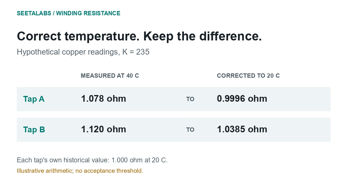
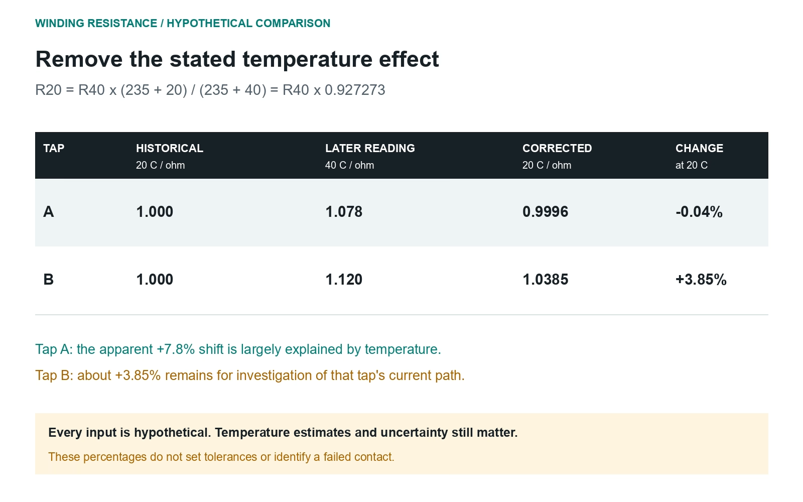
In this hypothetical case, a copper winding measures 1.000 ohm at 20 C. Later, the same terminal pair and tap gives 1.078 ohm at 40 C. Correcting to 20 C:
1.078 x (235 + 20) / (235 + 40) = 0.9996 ohm
The stated temperature difference largely explains the apparent 7.8% increase. This demonstrates arithmetic, without establishing a tolerance or validating the temperature estimates.
Another tap measures 1.120 ohm at 40 C against its own 1.000-ohm history at 20 C. Corrected resistance is 1.0385 ohm, leaving about 3.85% difference for investigation.
Request a repeat, confirm tap mapping and review uncertainty and service history. Adjacent results cannot resolve the local difference or identify the responsible component.
4. Turn the Test Into a Useful Maintenance Record
Keep measurements, corrections and suspected causes separate. Missing and out-of-range readings are not zero resistance.
Attach raw and corrected values to the condition-monitoring record. Where heating is suspected, DGA may add context, without locating a resistive joint by itself.
The review should identify the terminal pair, tap, evidence gaps and next check. Operating decisions need the broader asset assessment.
Talk to an engineer about the next evidence needed.
Sources and scope: IEC 60076-1:2011, clauses 11.2.1-11.2.3 and Annex E, earlier local full-text review; Megger, Q and A: Winding Resistance Testing (2019); OMICRON, The DC Winding Resistance Test: In-Depth (2018), pages 10 and 14. Public sources rechecked 29 September 2026. Examples and table are original.