Does a difference between SFRA traces indicate winding displacement in a transformer?
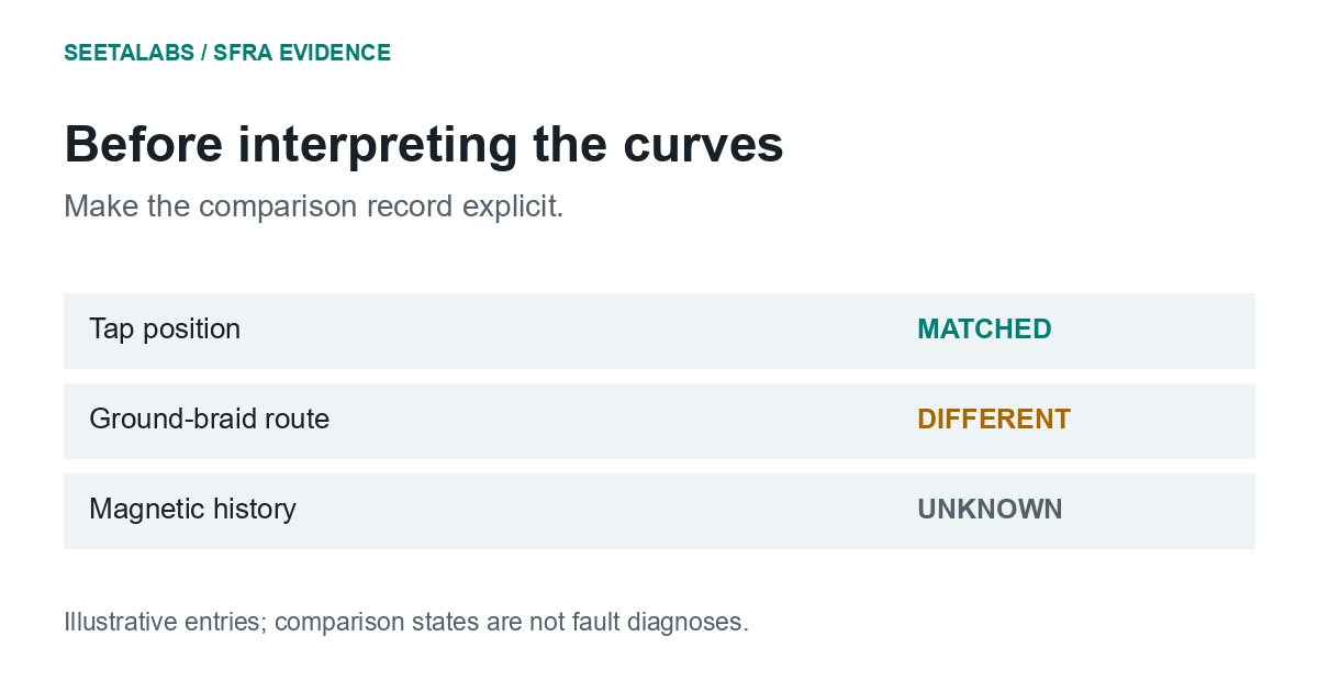
Not by itself. A trace difference supports a diagnosis only after the reference is shown to be comparable in terminals, tap positions, connections, grounding, assembly state and magnetic history, and after the difference survives a documented repeat. Mark each setup field as matched, different or unknown, keep all traces, and send any repeatable residual with the event history and winding design for specialist interpretation.
A difference between transformer SFRA traces needs a comparable reference before it can support a diagnosis. Check configuration, connections and magnetic history, then establish whether the difference survives a documented repeat. A report should show what was matched and what remains unknown.
1. Reconstruct the Reference Measurement
IEC 60076-18:2012 covers frequency-response measurement techniques and equipment for factory and field use. Only its catalogue scope was checked here.
Recover terminal identities, direction, tap positions, other-winding connections, grounding and whether bushings and oil were present. "Factory baseline" alone leaves these fields unanswered.
Uhrig and Radler's reproducibility paper demonstrates effects of connections, taps and residual magnetisation. It favours a same-unit historical reference; phase and sister-unit comparisons require allowance for design differences.
Give each field a state: matched, different or unknown. Keep the source file or photograph beside the entry so another reviewer can recover the evidence.
2. Test Repeatability Before Interpreting the Difference
Ask the qualified test team to preserve raw files and repeat under its approved procedure. Record whether leads were left in place or rebuilt; those checks address different aspects of repeatability.
This original investigation table contains no pass/fail limits.
| Pattern in the evidence | Competing explanation | Review that reduces ambiguity |
|---|---|---|
| Difference disappears after setup correction | Measurement arrangement | Retain both records and correction |
| Difference follows a tap change | Winding configuration | Compare matching positions |
| Difference follows DC testing | Magnetic state | Check sequence and demagnetisation record |
| Same-unit baseline unavailable | Design variation | Seek factory files; qualify substitutes |
| Difference persists with matched setup | Internal change remains possible | Specialist review and complementary tests |
Frequency bands alone cannot identify the cause. Interpretation depends on transformer design and the complete response.
3. Worked Example: A Post-Transport Curve That Moves Twice
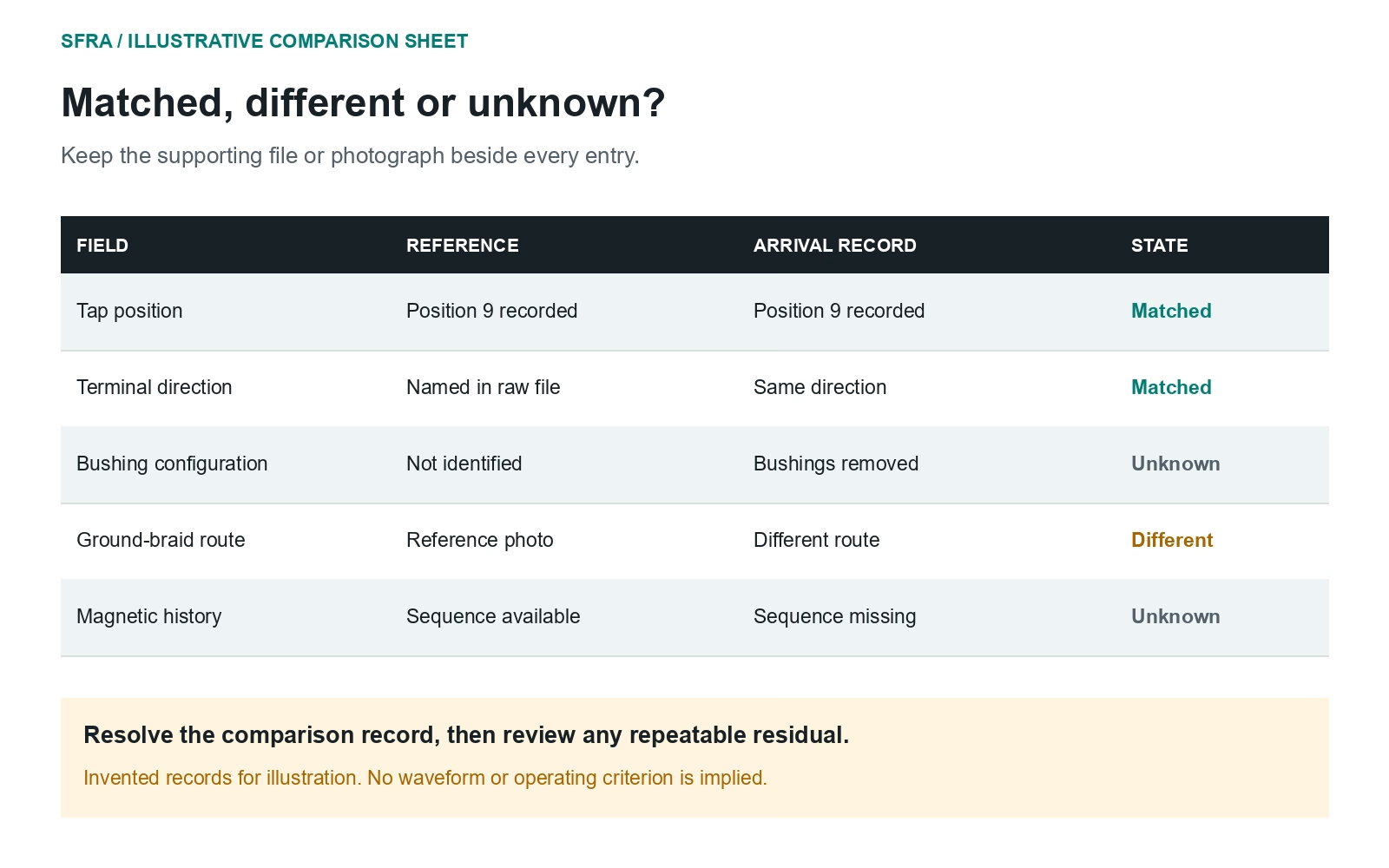
In this hypothetical case, the arrival trace differs from the factory trace. The first report suggests winding displacement. The transformer travelled with bushings removed, but the reference PDF does not identify its assembly state.
The reviewer finds a separate transport-configuration reference in the original test schedule. Comparing it with the arrival test resolves one mismatch. Photographs then reveal a different ground-braid route.
After the qualified team reconstructs the intended arrangement, much of the discrepancy disappears. A smaller repeatable deviation remains. The revised finding identifies two setup differences and an unresolved residual. Keep all three traces, with the reason for each comparison, so the investigation remains auditable.
An independent leakage-reactance comparison under equivalent conditions adds another measurement. Sweetser's paper on SFRA and leakage reactance presents cases using both methods and complementary diagnostics. Neither agreement nor disagreement removes the need to examine the full evidence.
4. Report the Strength of the Inference
Name the reference, repeated differences and unresolved setup fields. Send the residual finding, event history and winding design for specialist interpretation. Assign an owner and a next evidence request to each unresolved item.
In the condition-monitoring record, retain baseline limitations and the open mechanical question. An aggregate health index must leave that question visible.
The responsible engineer integrates test results, transport or fault history, OEM advice and the asset procedure before making an operating decision.
Talk to an engineer about the evidence needed for a wider asset review.
Sources and scope: IEC 60076-18:2012, catalogue scope only; the linked Uhrig/Radler and Sweetser papers, read directly on 29 September 2026. The hypothetical transport case and comparison worksheet are original. No universal diagnostic frequency boundary or operating limit is supplied.