
A turns-ratio result needs a verified reference: reported quantity, winding connection and actual tap voltage. A consistent error across phases can arise from an incorrect expected value. Resolve the inputs from independent records before interpreting the discrepancy.
1. Separate Nameplate Voltage Ratio From Winding Turns Ratio
Three-phase nameplates usually state line-to-line voltages. Their relationship to individual winding voltages depends on the connections. A tester may already apply the relevant conversion.
Carreno and Chhajer's turns-ratio paper explains nameplate, measured voltage and turns ratios. Identify the displayed quantity before adding your own correction.
IEC 60076-1:2011, clause 11.3, addresses voltage-ratio measurement at each tapping and checking the connection symbol or polarity. It was checked in the earlier local full-text review; acceptance provisions are not reproduced here.
Unusual arrangements, inaccessible neutrals, autotransformers and phase-shifting transformers require their own diagrams and approved procedures.
2. Make the Expected Value Auditable
Obtain the nameplate tap schedule, identify the tapped winding and check the tester's position labels. Position numbers alone cannot establish the expected ratio.
Use this original table to locate evidence gaps.
| Record discrepancy | Possible explanation | Evidence needed before a verdict |
|---|---|---|
| Similar error across phases | Expected value or configuration | Nameplate, diagram and tester setup |
| Error varies systematically with tap | Tap schedule or mapping | Expected voltage at each position |
| Ratio agrees; phase result differs | Mapping or configuration | Phase convention and vector group |
| One phase differs on repeat | Local issue remains possible | Excitation data and other tests |
| Result changes with excitation | Method sensitivity | Applied voltage and instrument guidance |
Check how the tester treats vector-group displacement and residual phase error. Preserve current with applied voltage, frequency and connections; a separate exciting-current test may use different conditions. Carreno and Chhajer discuss voltage dependence in section 3.
Record prior DC testing and demagnetisation. OMICRON's presentation, page 10, explains how residual magnetism can affect ratio and other tests.
Keep any reference correction and its supporting evidence in the audit trail. A change made only to obtain a passing result has no evidential basis.
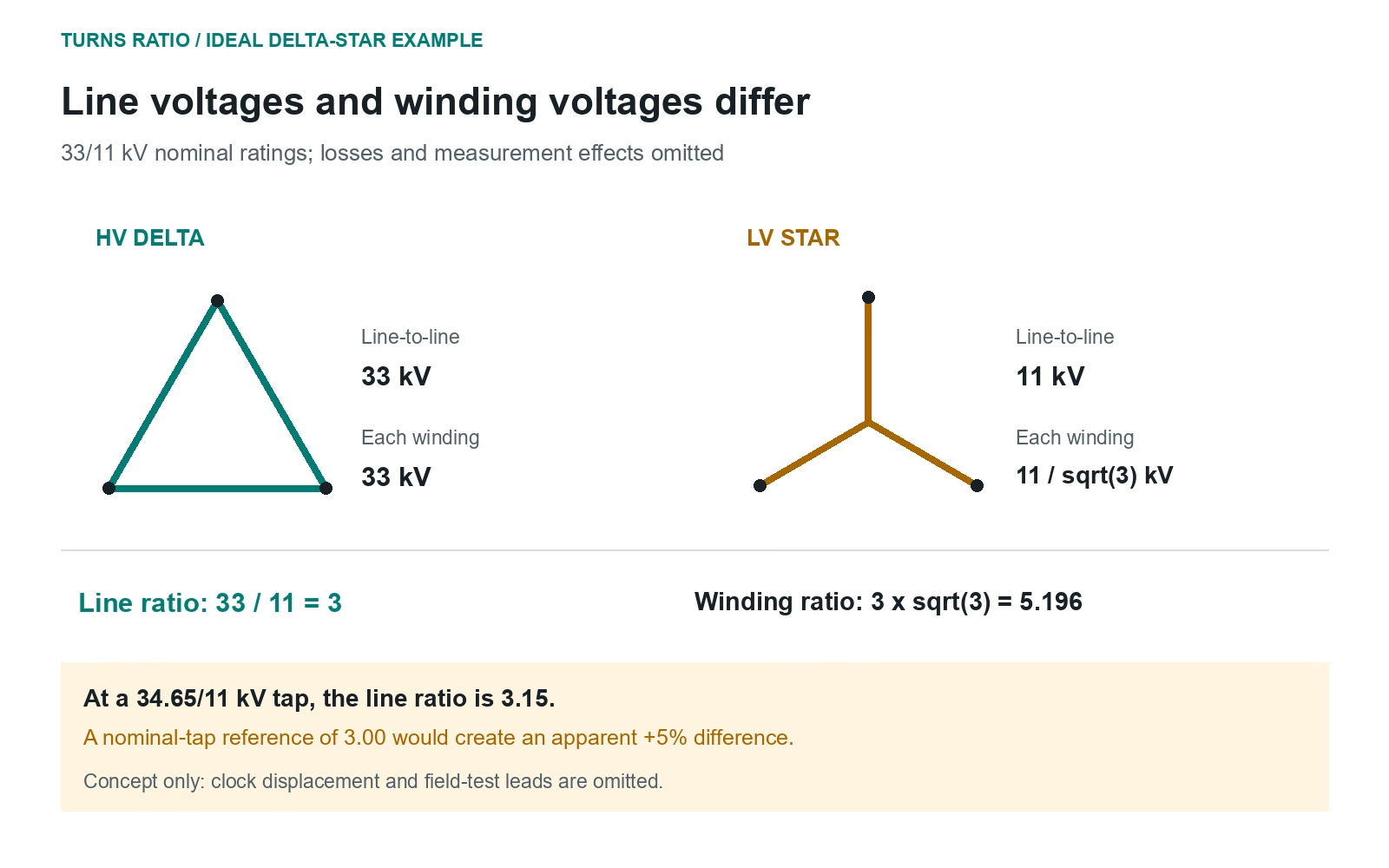
3. Worked Example: Two Correct Ratios for One Transformer
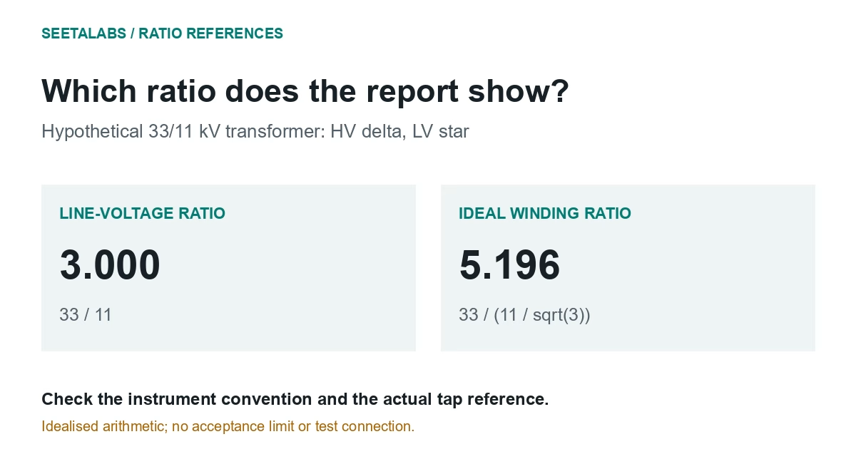
Consider a hypothetical 33/11 kV transformer: HV delta, LV star. For this idealised calculation, ignore losses and measurement effects.
The line-voltage ratio is 33/11 = 3. Each HV phase winding sees 33 kV; each LV phase winding sees 11/sqrt(3) kV. The corresponding winding turns ratio is:
33 / (11 / sqrt(3)) = 5.196 approximately
A display of equivalent line-voltage ratio can therefore show about 3, while the corresponding winding-ratio reference is about 5.196. Check the instrument convention before comparing them.
At a hypothetical 34.65 kV HV tap with the same 11 kV LV rating, the expected line-voltage ratio is 3.15. Comparing it with the nominal-tap reference 3.00 creates a 5% discrepancy. The first question is whether the recorded tap supports 3.15.
These calculations supply references, not acceptance limits. A persistent discrepancy after configuration review still requires technical assessment. Retain the original reported error and the corrected calculation together.
4. Define What a Successful Ratio Test Does Not Prove
A satisfactory ratio cannot settle every winding-condition question. Megger's mechanical-integrity discussion describes complementary winding and mechanical tests. A severe event or suspect contact still needs its own investigation.
Keep findings in the condition-monitoring record. An abnormal gas trend also remains a question for DGA assessment, even when the ratio is satisfactory.
Pair each result with expected value, tap and vector configuration so the responsible engineer can apply the correct specification.
Talk to an engineer about unresolved comparison evidence.
Sources and scope: IEC 60076-1:2011 clause 11.3, earlier local full-text review; Carreno/Chhajer, NETA 2019, sections 1-3; OMICRON's 2018 presentation, page 10; Megger's 2020 mechanical-integrity article. Public sources rechecked 29 September 2026. Examples and review table are original.