Does a hotter transformer terminal on an infrared image mean a defective connection?
Not automatically. Surface finish, emissivity, reflection, viewing angle, phase current, loading and cooling can all make one terminal look hotter, and infrared inspection measures surface radiation, not internal winding hot-spot temperature. Compare matched surfaces with contemporaneous currents, keep the radiometric file and a visible-light image, and investigate reflection if the apparent hot region changes with viewing angle.
A hotter transformer terminal is not automatically a defective connection. Compare surface finish, phase current and viewing conditions first. Infrared inspection measures surface radiation, not internal winding hot-spot temperature. The report must explain which comparison supports the proposed investigation.
Read the Surface and the Measurement Settings
FLIR's guide to emissivity and reflected temperature explains why reflective metal can give misleading thermal readings. For measurement settings, including distance and intervening optics, see the FLIR thermography reference (PDF, section 2).
Preserve the radiometric file and a visible-light image. Identify the target: painted and shiny surfaces are not interchangeable. Record camera settings and viewing position; a default emissivity will not describe every surface.
For an infrared window, retain its transmission characteristics. A visible-light photograph does not establish a suitable thermal optical path.
ISO 18434-1:2008 covers condition-monitoring thermography, interpretation and compensation factors. Only its catalogue scope was reviewed here, not its full requirements or severity criteria.
Compare Loading and Cooling Before Ranking Anomalies
Record phase currents, recent loading, ambient conditions, sunshine, wind and fan or pump state. Fluke's electrical thermography guidance discusses loading and wind cooling. No universal minimum-load percentage or generic temperature alarm is adopted here.
The original comparison table below is intended for a report reviewer.
| Thermal observation | Comparison that could mislead | Evidence to obtain |
|---|---|---|
| One terminal appears hotter | Different surface finishes or phase currents | Matched target surfaces and contemporaneous currents |
| A reflective bolt changes appearance with viewing angle | Reflected heat mistaken for local heating | Alternative safe viewing position and reflection review |
| One radiator bank is cooler | Assuming cool always means healthy | Valve arrangement, fan state and circulation context |
| Tank surface temperature increases | Treating surface temperature as winding hot spot | Load history, oil indications and cooling performance |
| A previous anomaly is absent at lower load | Declaring repair success from unmatched surveys | Comparable operating conditions and maintenance evidence |
Do not average away a persistent local pattern or classify every asymmetry as a defective joint. Identify the explanation still to be tested.
Worked Example: Why Current Squared Is Not a Temperature Correction
Suppose two hypothetical connections carry 100 A and 150 A. With equal electrical resistance, their resistive heating powers follow P = I squared R:
P150 / P100 = (150 / 100) squared = 2.25.
This is a power ratio under an equal-resistance assumption, not a temperature ratio.
Surface temperature also depends on heat transfer, surroundings, geometry and time at load. Dividing an infrared temperature by current squared is not a generally valid acceptance correction.
If the hotter connection is shiny and the reference painted, loading and radiometric behaviour both differ. A precise temperature difference cannot isolate a defect while both remain uncontrolled.
Obtain comparable surface observations and contemporaneous currents from approved sources. A persistent local pattern supports focused investigation. If the apparent hot region changes with viewing angle, investigate reflection before assigning a component temperature.
This is not an instruction to approach energised equipment or attach tape to live parts. Access and surface preparation require the site's authorised electrical-safety procedure.
Turn the Image Into a Testable Finding
Name the component and measurement area; attach the radiometric file, visible image, phase currents and comparison target. State which surface or operating differences remain unresolved.
For suspected cooling problems, review circulation and cooling controls rather than assuming a terminal defect explains the pattern.
Bring the finding into transformer condition monitoring alongside load and cooling records. Dissolved gas analysis may provide complementary internal evidence, but a quiet gas result does not automatically resolve an external connection concern.
Thermography alone does not grant operating clearance.
Talk to an engineer about reviewing the evidence behind a thermal finding.
Sources and scope: ISO 18434-1:2008, official catalogue only; FLIR, How Does Emissivity Affect Thermal Imaging? and thermography reference T810442, section 2 (replacement references checked 2 October 2026); Fluke, Using Thermal Imaging Cameras for Electrical Inspections. Public guidance read 29 September 2026. Comparison table and numerical example are original, not normative acceptance criteria.
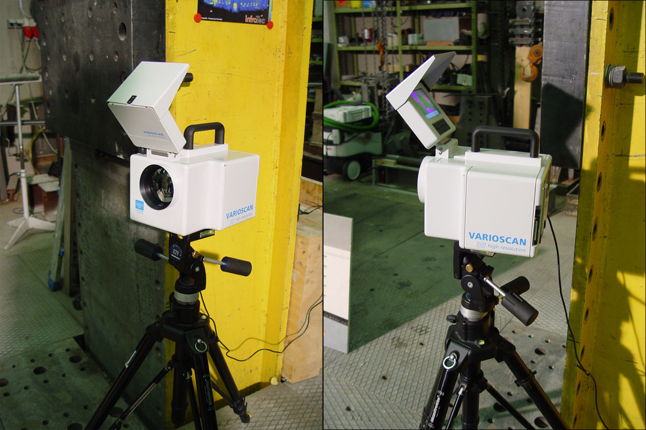
Cover photograph: Thermal imaging camera; illustrative equipment, not a measured survey. Mnolf / Wikimedia Commons, CC BY-SA 3.0. Source: https://commons.wikimedia.org/wiki/File:Thermal_camera.jpg