
OLTC dynamic testing examines the transition between tap positions, which stable endpoint readings cannot describe fully. An unusual trace warrants investigation but does not by itself identify worn contacts or a defective transition resistor. Name the transition, direction, repeatability and measurement method before proposing a repair.
Ask What the Instrument Actually Recorded
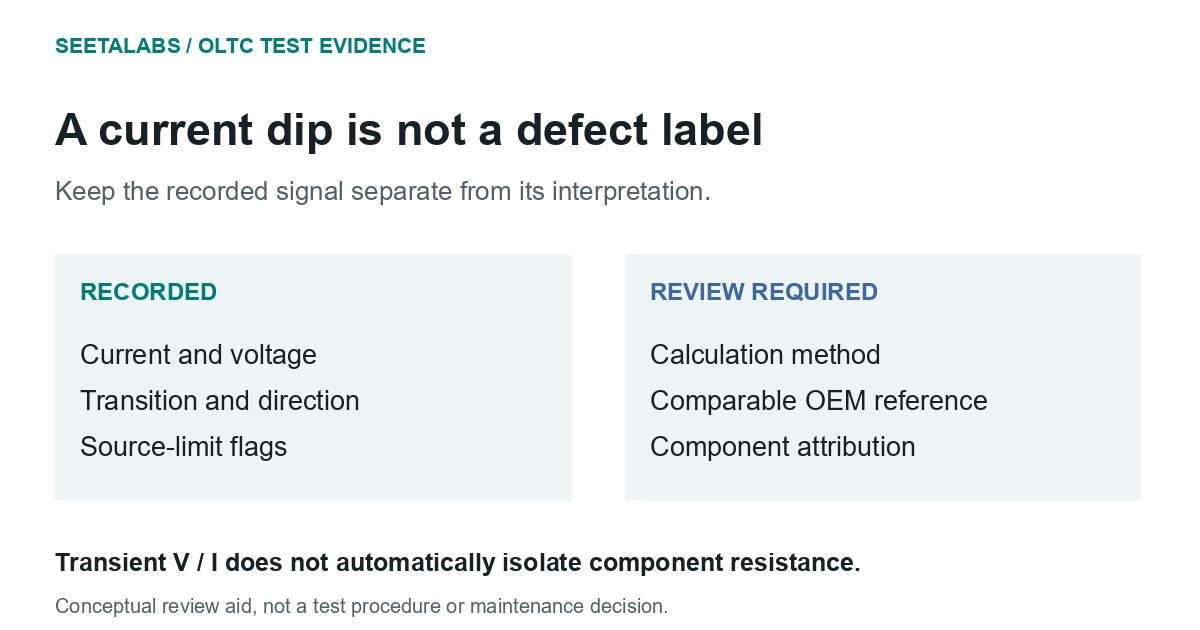
Obtain the original current and voltage records, calculated resistance, sampling settings and instrument method. Megger's technical guidance distinguishes a ripple test, which characterises a current dip, from more detailed dynamic measurements. A percentage current change is not a measured transition-resistor value.
Dividing transient voltage by current does not necessarily isolate transition resistance. Voltage can include an inductive contribution or be limited by the test source. CIGRE TB 962 (2025), Appendix F, pages 174-175, discusses these effects. Ask how processing treats induced voltage, winding resistance and source limits before interpreting a trace as component resistance.
Identify resistor or reactor design, vacuum or oil switching, model, tap schedule and maintenance instructions. IEC 60214-1:2014 covers tap-changer performance and tests; only its catalogue scope was reviewed, not detailed waveform criteria.
OMICRON's tap-changer guidance describes dynamic measurements and motor-current analysis alongside static contact assessment. Keep these complementary observations separately identified.
Compare Transitions That Should Be Comparable
"Tap 8 abnormal" does not say whether the anomaly occurred entering, leaving or resting on that position. Record start, finish, direction, operation number and any corresponding motor record.
This original maintenance-review matrix organises the evidence without assigning generic defect labels.
| Observation | What it supports | Evidence needed before specifying maintenance |
|---|---|---|
| Repeated anomaly on the same transition and direction | A transition-specific issue deserves review | Comparable reference trace and OEM interpretation |
| Similar change on every transition | A common influence may exist | Test settings, source behaviour and drive supply |
| Dynamic anomaly with stable static endpoints | Endpoint measurements do not explain the transition | Timing, current/voltage traces and switching sequence |
| Abnormal motor-current record with a trace change | Drive behaviour is relevant | Supply-voltage record and mechanical-drive review |
| Single anomaly that cannot be reproduced | Observation remains unresolved | Raw data, connection checks and controlled repeat |
Expected shapes depend on the switching design: ask the manufacturer which transitions are comparable. Retain individual events and their sequence; averaging can hide an intermittent anomaly.
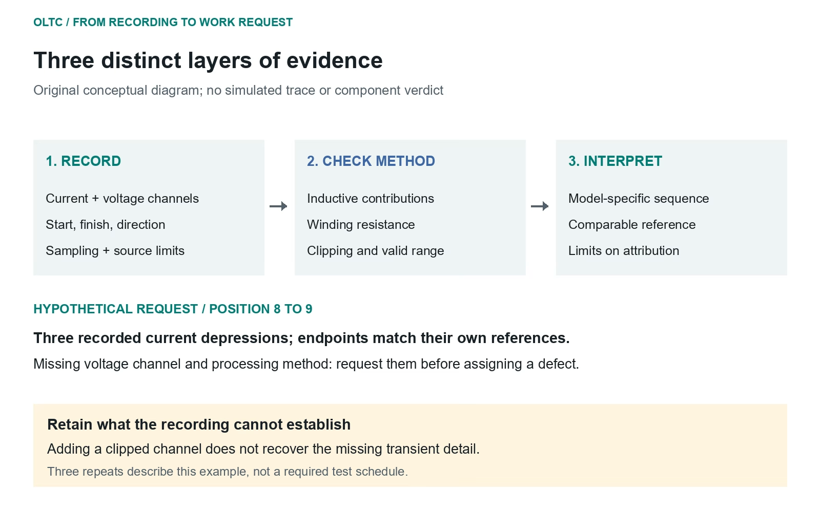
A Hypothetical Work Request That Can Be Acted On
Suppose an invented test sequence shows an unusual current depression on three repeated operations from position 8 to 9. The reverse operation does not show the same shape. Static resistances at both endpoints remain consistent with their own references after temperature treatment.
The initial work order says "replace worn contacts." That exceeds the evidence: directional differences may be design-dependent. The export also lacks the voltage record and calculation method needed to assess a claimed resistance value.
A useful request attaches all three traces and the endpoint results, requests the missing channel, source-limit information and drive-supply record, and asks for comparison with the manufacturer's expected sequence. A clipped recording cannot recover missing transient detail merely by being added to the report.
This is a hypothetical work request, not a claim about a particular OLTC or a recommended number of repeat operations. Any additional operations must be authorised within the test plan.
Keep Compartment Evidence and Maintenance Authority Clear
Identify the oil-sampling compartment and whether it communicates with the main tank. The DGA guide provides context, not permission to transfer main-tank interpretations to a separate switching compartment.
Retain operation counts, maintenance history and model-specific requirements in condition monitoring. A missing baseline is not proof of normal switching; a trace alone cannot quantify remaining contact life.
Define the maintenance scope only after reviewing the model-specific transition evidence. Operation, inspection and intervention decisions remain with the responsible engineering team.
Talk to an engineer about the assessment evidence.
Sources and scope: IEC 60214-1:2014, catalogue scope only; CIGRE TB 962 (2025), Appendix F, pages 174-175, from the earlier documented local full-text review; Megger, Transformer Winding Resistance Testing, FAQ; OMICRON, Tap Changer Analysis. Public sources rechecked 29 September 2026. Matrix and work-request example are original.