
Bushing capacitance and tan delta changes raise two questions: are the results comparable, and does a repeatable difference remain? Start with bushing serial number, C1 or C2 circuit, temperature treatment and test settings. A transformer asset number cannot establish continuity after bushing replacement.
This is a record-interpretation guide, not a field procedure or acceptance table. An authorised test team must follow the manufacturer's instructions for testing and restoring taps.
1. Identify the Insulation Circuit Before Comparing Values
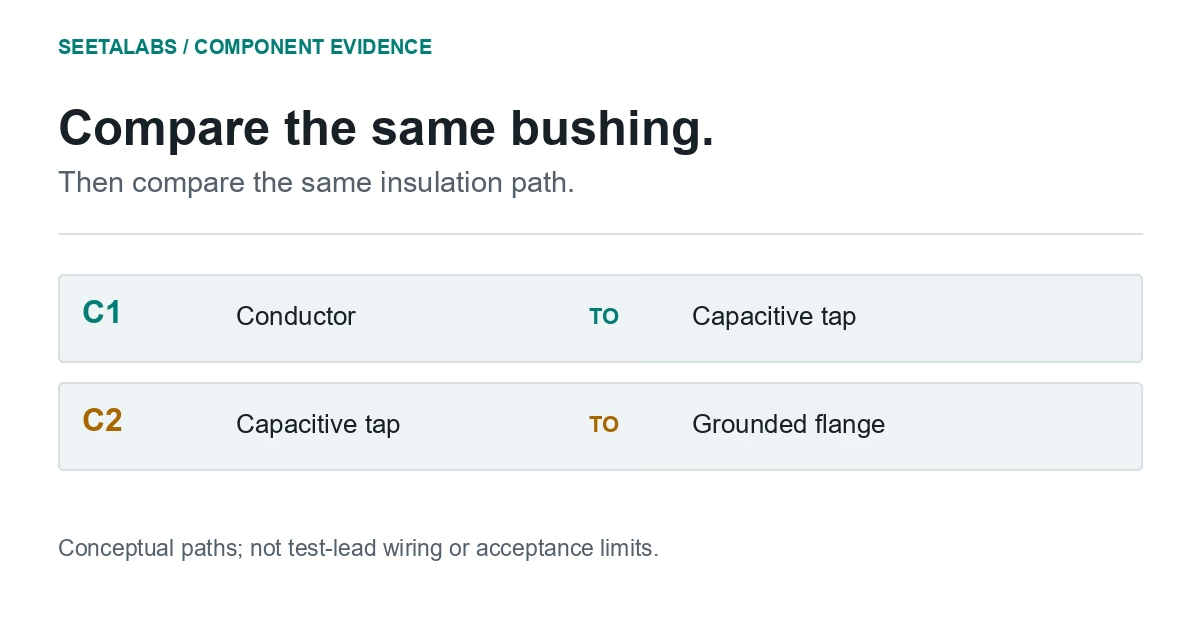
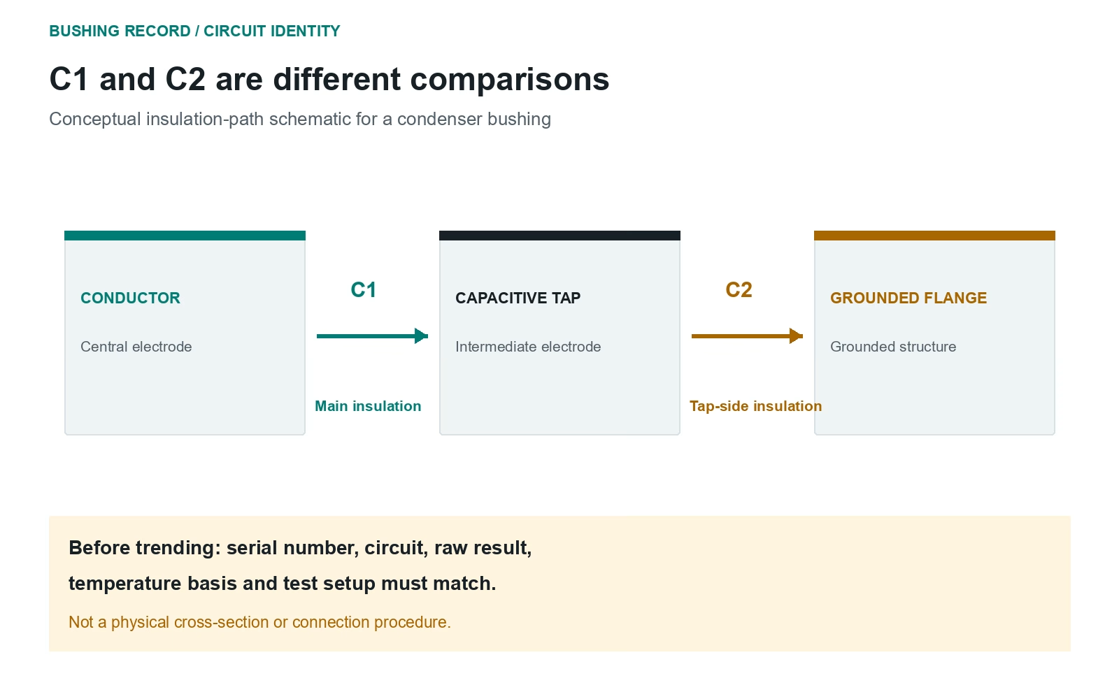
C1 and C2 are different circuits. In a condenser bushing, C1 represents main insulation between conductor and tap; C2 represents insulation between tap and grounded flange. A result labelled only "bushing capacitance" is incomplete. OMICRON's technical presentation explains the circuits and C2's sensitivity to the tap environment.
Record design, phase and replacement history. Power factor and dissipation factor (tan delta) are related but not identical; preserve original labels and whether values are fractions or percentages.
IEC 60137:2017 covers insulated bushings and their tests. Only its catalogue scope was checked here; manufacturer-specific field criteria remain essential.
2. Separate a Measurement Change From an Insulation Change
Keep raw and temperature-corrected results together. Check that the correction method applies to the insulation design. Megger's discussion notes that temperature dependence changes with insulation condition.
The original table below is a review aid, not an acceptance table.
| Observation | Question to resolve | Useful next evidence |
|---|---|---|
| Tan delta changes; capacitance stable | Were temperature and correction comparable? | Raw results and correction provenance |
| Capacitance and tan delta both change | Same serial number and circuit? | Nameplate and controlled repeat |
| C2 changes while C1 is stable | Could tap area or setup explain it? | Tap and setup review |
| All phases shift after changing contractors | Did the method change? | Instrument settings and comparison test |
| One bushing keeps changing | Is the trend component-specific? | OEM review and repeat results |
Do not average away a component-specific change, or infer three defects before checking a shared method change.
3. Worked Example: A Large Percentage Change With Missing Context
In this hypothetical example, C1 capacitance moves from 400 to 408 pF: +2%. Tan delta moves from 0.30% to 0.45%: +0.15 percentage points, or +50% relative. Neither change is an acceptance threshold.
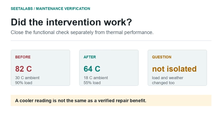
The first test was at 20 C; the second at 35 C. Contractors used different corrections and the older raw result is missing. "50% deterioration" is therefore unproven.
Reconcile the loss-factor comparison, then check whether the C1 difference persists under a documented repeat. If repeatable, report it with measurement uncertainty and design history; keep the historical tan delta comparison unresolved.
4. Carry the Finding Into the Asset Review
Handover needs serial number, circuit, raw readings, correction, conditions, repeatability and open questions. An omitted or out-of-range result is not zero.
Record the tap's as-left condition separately. Before return to service, the authorised team must verify the OEM-specified earthing or approved monitoring termination and sealing. A good C1 result does not prove correct tap restoration. CIGRE TB 755 (2019), sections 4.1.3 and 5.5.2, discusses tap contact, sealing and monitoring connections; it is not a wiring instruction.
Carry unresolved findings into condition monitoring. A favourable oil result or aggregate score cannot resolve them. Submit comparable measurements and gaps for OEM review; this example provides no operating criterion.
For wider asset-assessment questions, contact SEETA Labs.
Sources and scope: IEC 60137:2017 catalogue scope; CIGRE TB 755 (2019) sections 4.1.3 and 5.5.2 in the locally held text; OMICRON, Bushing Power Factor Testing: In-Depth, especially pages 23-26; Megger, 1 Hz Testing: A New Dawn in PF Testing. Public sources rechecked 29 September 2026. Table and example are original.